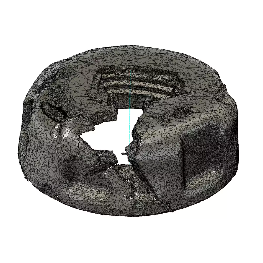
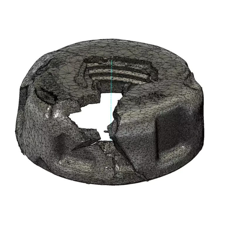
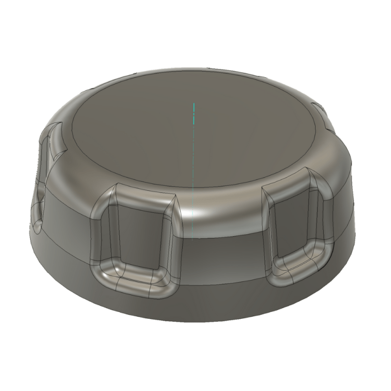
Reverse engineering a broken object is the process of creating a digital model of a physical object using 3D scanning, laser scanning, or photogrammetry. Once the digital model is created, it can be used to create a replacement part for the broken object. In this case, we reverse-engineered a broken cap using a 3D scanner. The scan mesh was damaged in multiple areas, so we cleaned, remeshed, and optimized it before remodeling.
Cleaning the Mesh
After scanning the mesh, we cleaned it to remove unwanted artifacts or data points caused by noise, reflections, or occlusions. We used a variety of tools to fill holes, smooth the mesh, and reduce the number of vertices.
Remodeling the Cap
To remodel the cap, we first aligned the object’s axis. Then, using the sketch tool, we fitted splines to the mesh cross-section. Splines are curves defined by control points, which allowed us to create a smooth and accurate representation of the mesh.
Next, we used the “revolve” and “loft” commands to create the solid object. “Revolve” creates a solid object by rotating a profile around an axis, while “loft” creates a solid object by connecting two or more profiles with a surface.
To finalize the reverse engineering broken object, we edited and refined the solid object to create the final model. This involved using tools such as “Extrude” and “Chamfer.” Once the model was complete, we exported it from Fusion 360 and printed it on a 3D printer.
Reverse Engineering benefits
Reverse engineering can be used to create replacement parts for obsolete or damaged objects, improve the design of existing objects, create new products based on existing designs, and understand the design and functionality of complex objects. It is a valuable tool for businesses and individuals alike, as it can save time and money, improve product quality, and help develop new products.


